New diagnostic devices can identify when pressure incidents happen, while keeping an eye on the condition of pressure-relief valves and rupture disks
Any kind of pressurized system, from the hot-water heater in a residence to a massive chemical reactor, will have some sort of pressure relief mechanism. It's there to let internal pressure escape before it overcomes the mechanical strength of the equipment. This concept is as old as the earliest steam boilers, and its function is to protect people and equipment.
Early pressure-relief-valve (PRV) designs were simply openings held shut by weights. Modern versions are more sophisticated, using springs that can be fine-tuned to open at very specific pressure setpoints and pilot-operated valves that bring a higher level of stability to avoid chattering. PRVs come in a variety of sizes and need to be matched with the overall size of the system and its ability to generate pressure. If pressure can't be released faster than it can be generated, the valve is too small. If the valve is too large, it could become unstable during a release.
A relief system for a process unit generally involves more than one PRV. System design guidelines are covered in the ASME Boiler and Pressure Vessel Code (BPVC), Section VIII. It provides detailed explanations of the variables involved in creating an overall system based on the maximum allowable working pressure for the equipment and a range of other variables. Naturally, design of a relief system should be left to experts, given the importance it has in the overall safety strategy for a plant or facility.
Pressure relief options
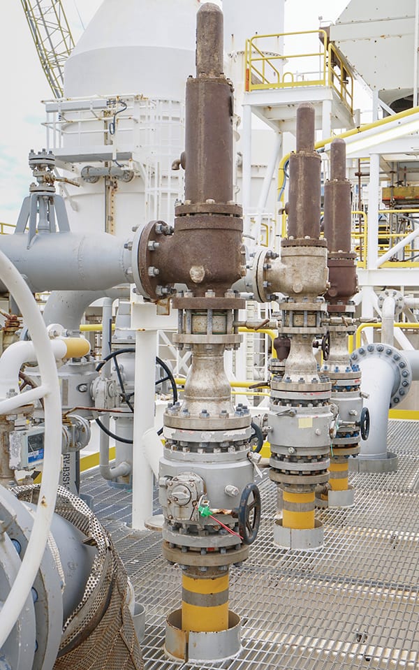
Conventional PRVs (Figure 1) are useful in situations where overpressure incidents are common or even routine, since they can re-seal themselves when the pressure recedes. If working correctly, no maintenance action is necessary to resume normal operation. However, as we will soon discuss, the functionality of a given valve or a system overall can be difficult to evaluate without sending operators out to manually inspect each valve.

Figure 1. Pressure relief valves are available from a variety of sources in a vast range of sizes, all providing the same basic functionality
Emerson Automation Solutions
PRVs are mechanical and do not need any electronic components to function. Consequently, they don't have any built-in mechanism capable of reporting their condition or activity. If operators want to know what is happening with a given system, they typically depend on watching normal process pressure measurements for indication of operation near the PRV's setpoint.
PRVs are not the only relief mechanism. A rupture disk can provide a less expensive, but more maintenance-intensive solution. As the name implies, in the event of an incident, the disk splits open and releases the pressure contained in the system. The action is drastic, and the process will certainly have to be shut down, because once a disk is ruptured, it cannot reseal itself. Rupture disks are typically made of relatively thin metal, usually stamped or scored to allow them to split at a specific pressure. In some cases, they have been known to develop pinhole leaks, allowing release of the process fluids.
Like PRVs, rupture disks have no built-in mechanism for reporting their condition or functionality. Usually, operators recognize an incident by a significant loss of system pressure. Some users place a mechanically activated switch on the back side of the disk to indicate rupture.
Pressure relief systems might release the contents to atmosphere if the products involved are environmentally benign, but more often, individual relief points feed into a system to collect liquids, while sending gases to a scrubber, recovery system or flare. Any product released will typically be unrecoverable or recovered for a less noble application, such as feeding energy to boilers and furnaces. This loss adds to the cost of an incident, along with possible environmental consequences and fines. Since the header connection covers the outlet of either type of device, it may not be clear to operators trying to troubleshoot the situation which valve or disk has opened if the answer is not identifiable from normal process operating information.
Monitoring relief devices
Monitoring the condition and activity of PRVs and rupture disks should be a part of normal plant operation, but as previously mentioned, there are no mechanisms within the devices capable of sending information to an automation system. Creating a monitoring device borrows from traditional maintenance techniques: listening.
"Old-timer" maintenance technicians can diagnose a device by sticking a screwdriver against it and putting an ear to the handle. More sophisticated individuals might carry a stethoscope-type device or a hand-held instrument, both of which are designed to capture ultrasonic sounds. These need to be applied directly to the subject device by an operator, so they aren't suitable for permanent, continuous monitoring.
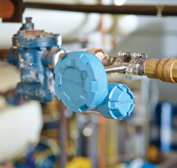
Acoustic monitoring devices (Figure 2) are now available that are designed for mounting directly to pipes adjacent to valves, PRVs, steam traps and other common fluid handling equipment. They capture sounds transmitted directly through the metal at high frequencies, above human hearing limits, so ambient noise is not a concern.
Fluids flowing through the devices mentioned make various sounds, particularly when some part of the mechanism is affected. For the purposes of this discussion, we'll concentrate on how acoustic monitoring devices can identify characteristic sounds of PRVs.

Figure 2. An acoustic monitoring device listens to an adjacent device. It can be programmed to identify characteristic sounds and report its evaluation via a WirelessHART network
Emerson Automation Solutions
A slow leak
A PRV retains its seal by having a spring hold the stem against the seat. A fully-closed valve makes no noise because nothing is flowing through it. When the system pressure exceeds the setpoint, it opens, releasing the contents of the system – either liquid, gas or both. This creates turbulence, generating noise that an acoustic monitor can hear and report to the automation system.
If the system pressure is sufficiently relieved or the process is adjusted to reduce it, the valve should close again. If everything is working correctly, it will seal and the noise will cease. Data from the acoustic monitor can report the time the discharge began and ended, while giving some indication of how serious the discharge was based on the amplitude of the sound.
The problem many plants face is getting the valve to reseal. Since overpressure incidents are often related to process upsets, particulate matter in vessels and pipes can be stirred up and blown out with the contents. Some particles can lodge in the valve seat and keep it from closing entirely, leaving it in a perpetually leaking state, which operators call "simmering." This leakage may not be enough to cause problems with the process, but it does release product that must be handled by the unit's pollution control systems.
A knowledgeable operator might be able to infer which valve is simmering from process data, but often, it can take some time for personnel to realize there is a problem at all, much less where it might be happening in a complex system with many PRVs. An acoustic monitor will hear the simmering, even if it is very slow. Operators checking the monitors can tell immediately if a given PRV has fully reseated itself after an incident. Maintenance then decides when to address the issue based on the cost or danger of the product and the volumes involved.
Chattering can be the cause and result of valve damage. If a valve is too large for the application or goes through a long but slow period of overpressure, it may open and close many times, beating the sealing surfaces together, scratching the seat and valve or bending the stem. A displacement of hundredths of a millimeter can create a gap capable of releasing pressure, but is also detectable by an acoustic monitor.
Combination installations
PRVs are sophisticatedly designed and carefully calibrated, so they can be very expensive – especially large sizes and units made in special corrosion-resistant alloys. By comparison, rupture disks are much cheaper. Some users install a rupture disk and a PRV in series on the same vessel. The disk faces the process while the PRV backs it up, so the disk has a slightly lower pressure limit than the PRV. This provides a best-of-both-worlds arrangement:
- After an incident, the rupture disk will be blown, but the PRV can reseal itself, allowing the process to continue operating until the disk can be scheduled for replacement.
- The rupture disk is the only part exposed to the process, so if special alloys are necessary, only the disk needs to be purchased in the expensive material. The PRV should have sufficient corrosion resistance so it can be exposed to the process for an extended period, at least long enough to allow the process to be shut down and the disk replaced.
- This combination system requires effective monitoring for the reasons delineated above, and because it is required under the ASME standard.
Avoiding a serious problem
The biggest drawback to this type of combination installation is the potential for failure during an incident. Here's how: there must be an interstitial space between the rupture disk and PRV since they cannot be up against each other. This is a sealed space because anything coming through a blown disk needs to pressurize the PRV so it will open and allow the contents to release to the collection system.
The interstitial space needs to be at atmospheric pressure because rupture disks are normally rated for release to atmosphere. If the space between the two devices has greater than atmospheric pressure, the trapped pressure will press against the back of the disk, and it will not rupture until system pressure has reached the burst point plus the interstitial space pressure.
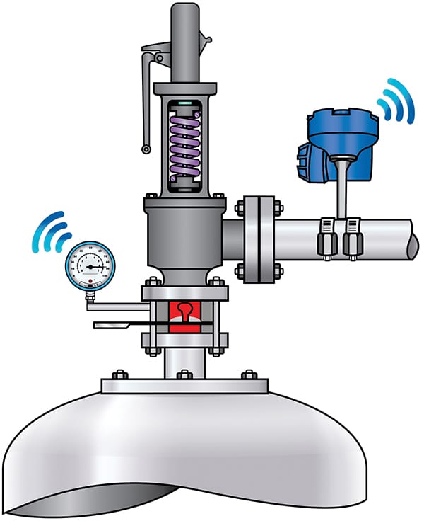
Rupture disks do occasionally develop microscopic pin-hole leaks, typically caused by extended operation near burst pressure. If this happens, gas or liquid can leak through (Figure 3), equalizing pressure on both sides of the rupture disk, and ultimately reaching full system process pressure. Under such conditions, the rupture disk may no longer serve its desired function as the weakest link in the containment chain. Consequently, ASME BPVC Section VIII UG-127 specifies that any installation using a combination rupture disk and PRV system must have an indicator to monitor the pressure of the interstitial space to detect a disk rupture or leakage.

Figure 3. If pressure develops between the disk and the PRV, it will not blow out at the design pressure. A pressure gage can warn if pressure goes above atmospheric
Emerson Automation Solutions
This function can be performed by something as simple as a mechanical gage or even a try cock provided an operator passes by on rounds at appropriate intervals. The other extreme is using an electronic pressure transmitter sending its data to the unit's distributed control system (DCS) or safety-instrumented system (SIS) via a wired connection. This is arguably best, but also the most expensive solution.
There is a middle-ground approach that accomplishes both, but without the high cost. There are electronic pressure gages capable of providing a local display while also sending data via a WirelessHART network. Operators can read the device while on rounds, but it can also provide an alarm to the automation or safety systems if desired. These can be added without installing new cabling or adding I/O slots to the process automation system.
Monitoring via wireless networks
Acoustic monitors and electronic pressure gages can use the same WirelessHART network as other wireless field devices (Figure 4). This allows pressure-relief system monitors to interface with a larger automation system, while also sending data to the maintenance team. With continuous monitoring, technicians can tell in an instant if a pressure release is underway, if a valve has not fully resealed itself, or if a rupture disk is starting to fail.
New application software is a ready-to-use solution able to characterize a release event by interpreting information from an acoustic transmitter, eliminating graphic interpretation by operators and false positives. It also requires electronic acknowledgement of when and what action was taken after an event occurred. This is critical information for environmental compliance but also for a PRV maintenance program.
With prompt action, the overall effectiveness of the unit's safety system can be assured while avoiding product loss and potential environmental consequences. Many equipment condition monitoring devices are now available that can help determine how well many types of assets are functioning. This information can help optimize maintenance efforts and avoid costly unplanned shutdowns.

Figure 4. A WirelessHART network is self-organizing and can support a wide variety of process instruments and monitoring devices
Author
 Marcio Donnangelo is a global business development manager with Emerson Automation Solutions ( 6021 Innovation Blvd., Shakopee, MN 55379; Phone: 800-999-9307; Email: marcio.donnangelo@emerson.com.) and specializes in wireless technologies and digital transformation. He is an industrial electrical engineer with 25 years of field experience applying industrial automation solutions for customers across multiple business segments and industries, including petroleum refining, petrochemical, chemical, pulp and paper and others. He studied at FEI, the industrial engineering university, ETI Lauro Gomes, electronic technologist and former collaborator from Laboratório de Subsistemas Integráveis da Escola Politécnica da USP, all in São Paulo.
